
Engine management circuit diagram (Triumph Rocket III)
- Main
- Triumph
- Rocket
- Rocket III
- Engine and systems
- Fuel and control system
- Engine management circuit diag…
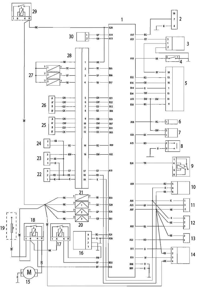
Key to wiring circuit diagram
| Key | item Description |
| 1 | Engine Control Module |
| 2 | Diagnostic Connector |
| 3 | Vehicle Speed Sensor |
| 4 | Sidestand Switch |
| 5 | instrument Assembly |
| 6 | Accessory Fuel Gauge |
| 7 | Gear Position Sensor |
| 8 | Clutch Switch |
| 9 | Starter Relay |
| 10 | Fall Detection Sensor |
| 11 | Air Pressure Sensor |
| 12 | MAP Sensor |
| 13 | Inlet Air Temperature Sensor |
| 14 | Lambda Sensor |
| 15 | Cooling Fan |
| 16 | Fuel Pump and Level Sender Assembly |
| 17 | Fuel Pump Relay |
| 18 | Cooling Fan Relay |
| 19 | Fuse Box (Fuse 7) |
| 20 | Ignition Coils |
| 21 | Evaporative Purge Valve |
| 22 | Throttle Position Sensor |
| 23 | Second Throttle Position Sensor |
| 24 | Inlet Air Temperature Sensor |
| 25 | Idle Speed Control Stepper Motor |
| 26 | Second Throttle Actuator |
| 27 | Fuel Injectors |
| 28 | Engine Harness Connector |
| 29 | Engine Management System Relay |
| 30 | Crankshaft Sensor |
Key to wiring colour codes
| Code | Wiring Colour |
| B | Black |
| U | Blue |
| N | Brown |
| G | Green |
| S | Slate/Grey |
| 0 | Orange |
| K | Pink |
| R | Red |
| P | Purple |
| W | White |
| Y | Yellow |
| LG | Light Green |
| LU | Light Blue |
ECM connector pin numbering
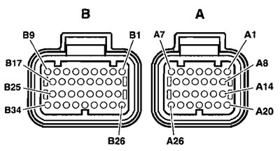
The above illustration shows the pin numbering system used in the engine management circuit diagram.
The small connector's pins are prefixed A and the large connector's pins B. As viewed on the mating face with the ECM (as per the illustration), pins are numbered from right to left with number one in the top right corner.
(The article is reprinted from this resource MotoInst.ru)
See this article in russian language
This article has been reviewed: Serafim Sazonov
Similar articles about motorcycles of other brands
Engine lubrication circuit Ducati ST2 (1997-2003)Engine starting system diagram Honda CB 400 SF (1992-1999)
Block diagram of the engine lubrication system Suzuki DRZ 250 (1996-2007)
Ignition system circuit diagram Yamaha FZ1 Fazer (2006-2015)
Removing the engine oil tank Aprilia RS 125/3 (1998-2005)
Comments and feedback from visitors
No comments yet, you will be the first!
- Information for owner
- Introduction to manual
- Engine and systems
- Engine repair
- Cooling system
- Lube system
- Fuel and control system
- Transmission
- Running gear and frame
- Frame and hinged elements
- Front suspension and handlebar
- Rear suspension
- Brake system
- Wheels and tires
- Electric equipment
- Equipment and devices
- Starting and charging system
- Electrical circuits